

Views: 0 Author: Site Editor Publish Time: 2020-10-24 Origin: Site
With the rapid development of the national economy and the increase in power demand, the country will vigorously promote the construction of a strong smart grid, and at the same time promote the rapid development of the electrical instrumentation industry. As an indispensable instrument in a strong smart grid, smart energy meters are in urgent need of the development of new products with the development of strong smart grids. Metallized film capacitors are widely cited as important components in smart meters. Capacitors for electric energy meters are professionally manufactured and developed together with China's electronic electric energy meter industry.
Metallized film capacitors:
Metallized film capacitors use organic plastic film as the medium, and metallized film as the electrode. The capacitor is made by stacking (except for laminated structure). The film used in metalized film capacitors includes polyethylene glycol and polynylon , Polycarbonate, etc., in addition to molecular weight, there are also laminated types. Among them, polyester film media and polypropylene film media are the most widely used.
Metallized film polymer uses polyester film or polypropylene film as a medium, and zinc aluminum alloy is attached to the surface of the film by vacuum evaporation to form electrodes. Capacitors are formed by non-inductive stepless substitution or laminated methods. Capacitors have high withstand voltage, high insulation resistance, good inductance frequency characteristics (smaller parasitic inductance), series ESR, high capacity stability, and low loss tangent.
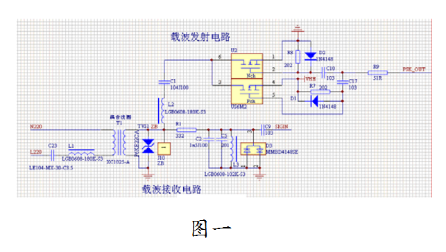
Metallized film capacitors, as their capacitors, have high insulation resistance, which can replace AC signals or pulse signals to the subsequent stage without attenuation, without affecting the DC operating point of the subsequent stage. As a step-down capacitor, the metallized polypropylene film capacitor has low loss tangent and high capacity stability (special process is used to prevent destructive corona from attenuating the capacitance), which can reduce the high AC voltage to meet the requirements of the subsequent circuit AC low voltage replaces the inverting transformer, making the product smaller and more stable.
This is the structure and principle of metallized film capacitors. Under its unique principle, the use of capacitors is more stable, so it is also increasing at the same time. Under such circumstances, it is beneficial to the comprehensive development of the capacitor industry. of.
Capacitor design principle and structure:
Metallized film polymer uses polyester film or polypropylene film as a medium, and zinc aluminum alloy is attached to the surface of the film by vacuum evaporation to form electrodes. Capacitors are formed by non-inductive stepless substitution or laminated methods. Capacitors have high withstand voltage, high insulation resistance, good inductance frequency characteristics (smaller parasitic inductance), series ESR, high capacity stability, and low loss tangent.
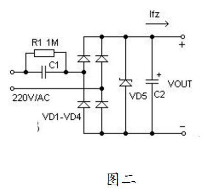
As a switching capacitor, the metallized film capacitor has high insulation resistance, which can replace the AC signal or pulse signal to the subsequent stage without attenuation, and at the same time does not affect the DC operating point of the subsequent stage (for example, C1, C2, C23). Metallized polypropylene film as a step-down capacitor due to its low loss tangent and high capacity stability (using a special process to prevent destructiveness), corona attenuates the capacitance), and can reduce the high AC voltage to meet the requirements of the subsequent circuit AC low voltage replaces the converter transformer, making the product smaller and more stable (for example, two C1).
Disadvantages and improvement of metallized film capacitors:
From a theoretical analysis, there should be no short-circuit failure mode for metalized film capacitors, while metal foil capacitors will have many short-circuit failure phenomena (such as 27-pbxxxx-j0x series). Although metallized film capacitors have the above-mentioned great advantages, compared with metal foil capacitors, they also have the following two disadvantages: First, the capacity stability is not as good as foil capacitors, because metallized capacitors are prone to loss of capacity under long-term working conditions And after self-healing, the capacity can be reduced. Therefore, if it is used in an oscillator circuit that requires high capacity stability, it is better to choose a metal foil capacitor.
Another major disadvantage is the poor ability to withstand large currents. This is because the metalized film layer is much thinner than metal foil, and the ability to carry large currents is weak. In order to improve the shortcomings of metalized film capacitors, there are currently improved high-current metalized film capacitor products in the manufacturing process. The main ways to improve are:
1) Use double-sided metallized film as electrode;
2) Increase the thickness of the metallized coating;
3) Improved welding process of end face metal to reduce contact resistance.
Precautions for using film capacitors:
1. Working voltage
The selection of film capacitors depends on the highest applied voltage, and is affected by the applied voltage waveform, current waveform, frequency, ambient temperature (capacitor surface temperature), capacitance and other factors. Please check whether the voltage waveform, current waveform and frequency at both ends of the capacitor are within the rated value before use.
2. Working current
The pulse (or AC) current through the capacitor is equal to the product of the capacitance C and the rate of voltage rise, that is, I=C&TImes;dt/dt.
Due to the loss of the capacitor, when used under high-frequency or high-pulse conditions, the pulse (or AC) current passing through the capacitor will heat the capacitor itself and cause a temperature rise, which will cause a risk of thermal breakdown. Therefore, the safe use of capacitors is not only limited by the rated voltage, but also by the rated current.
When the actual working current waveform is different from the given waveform, under normal circumstances, polyester film capacitors are used when the internal temperature rise is 10°C or less; polypropylene film capacitors are used when the internal temperature rise is 5°C or less In case of use, the surface temperature of the capacitor is not allowed to exceed the rated upper limit temperature.
The internal temperature rise formula of metalized film capacitor is as follows:
△T=I2rms*DF*ω/(β*S)
△T: The temperature rise inside the capacitor
Irms: the effective current value through the capacitor
DF: Loss tangent
ω: capacitive reactance (1/2πfc)
β: Film heat transfer coefficient
S: Capacitor surface area
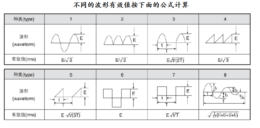
3. Conversion relationship of effective value of various waveforms
4. Capacitor charging and discharging
Since the capacitor charging and discharging current depends on the product of the capacitance and the voltage rise rate, even low-voltage charging and discharging may produce a large instantaneous charging and discharging current, which may cause damage to the performance of the capacitor. When charging and discharging, please connect a 20Ω/V~1000Ω/V or higher current limiting resistor in series to limit the charge and discharge current within the specified range. If there is a short-circuit charging and discharging of the capacitor, please include it in the scope of defective products and do not use it.
5. Flame retardancy
Although fire-resistant and flame-retardant materials-combustion-supporting epoxy resin or shells are used in the outer packaging of film capacitors, continuous external high temperature or flame can still deform the capacitor core and cause the package to crack, causing the capacitor core to melt or burn.
6. Ambient temperature
The rated operating temperature of the capacitor is 85°C. When the actual use temperature of the capacitor exceeds the rated use temperature (within the maximum use temperature range), the rated voltage of the capacitor will decrease as the temperature increases. Standard formula for reducing capacitor rated voltage:
VC=VR*(165-TA)/80
VC: Capacitor can withstand voltage at high temperature
VR: capacitor rated voltage
TA: Surface temperature rise of capacitor