

Views: 45 Author: Site Editor Publish Time: 2020-06-29 Origin: Site

When the frequency is high, the capacitance is no longer treated as a lumped parameter, and the influence of parasitic parameters cannot be ignored. Parasitic parameters include Rs, equivalent series resistance (ESR) and Ls equivalent series inductance (ESL). The actual equivalent circuit of the capacitor is shown in Figure 1, where C is the static capacitance and 1Rp is the leakage resistance, also known as the insulation resistance. The larger the value (usually above the GΩ level), the smaller the leakage and the more reliable the performance. Because Pp is usually very large (above GΩ level), it can be ignored in practical applications. Cda and Rda are dielectric absorption capacitance and dielectric absorption resistance, respectively. Dielectric absorption is a kind of internal charge distribution with hysteresis, which restores a part of the charge of a capacitor in an open circuit state after rapid discharge.
ESR and ESL have the greatest influence on the high-frequency characteristics of the capacitor, so the simplified model of series RLC as shown in Figure 1(b) is commonly used to calculate the resonance frequency and equivalent impedance:
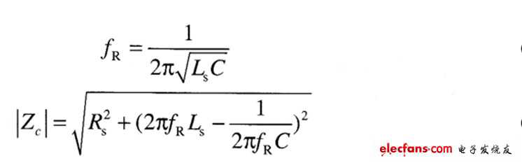
Figure 1: Decoupling capacitor model diagram

The frequency domain impedance diagram of the capacitor series RLC model is shown in Figure 2. The capacitor appears capacitive below the resonant frequency; inductive above the resonant frequency, the decoupling effect of the capacitor gradually weakens. At the same time, it is also found that the equivalent impedance of the capacitor decreases first and then increases with the increase of frequency. The minimum value of the equivalent impedance is the ESR occurring at the series resonance frequency.
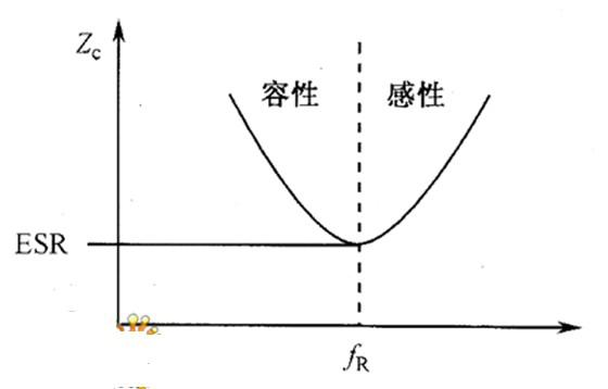
Figure 2: Frequency domain impedance diagram of the capacitor series RLC model
From the resonant frequency formula (4-8), it can be concluded that changes in capacitance and ESL value will affect the resonant frequency of the capacitor, as shown in Figure 3. Since the impedance of the capacitor at the resonance point is the lowest, the capacitor with fR and the actual operating frequency should be selected as much as possible in the design. In an environment with a wide operating frequency range, some large capacitors with small fR and small capacitors with large fR can be considered for mixing.

Figure 3: The effect of changes in capacitance and ESL on the frequency characteristics of the capacitor